Electrical Charge
Electricity
is the movement of electrons. Electrons create charge, which we can harness to
do work. Your lightbulb, your stereo, your phone, etc., are all harnessing the
movement of the electrons in order to do work. They all operate using the same
basic power source: the movement of electrons.
The three
basic principles for this tutorial can be explained using electrons, or more specifically,
the charge they create:
- Voltage is the difference in charge between two points.
- Current is the rate at which charge is flowing.
- Resistance is a material’s tendency to resist the flow of charge (current).
So, when
we talk about these values, we’re really describing the movement of charge, and
thus, the behavior of electrons. A circuit is a closed loop that allows charge
to move from one place to another. Components in the circuit allow us to
control this charge and use it to do work.
GeorgOhm was a Bavarian scientist who studied electricity. Ohm starts by
describing a unit of resistance that is defined by current and voltage. So,
let’s start with voltage and go from there.
Voltage
We define
voltage as the amount of potential energy between two points on a circuit. One
point has more charge than another. This difference in charge between the two
points is called voltage. It is measured in volts, which, technically, is the
potential energy difference between two points that will impart one joule of
energy per coulomb of charge that passes through it (don’t panic if this makes
no sense, all will be explained). The unit “volt” is named after the Italian
physicist Alessandro Volta who invented what is considered
the first chemical battery. Voltage is represented in equations and schematics
by the letter “V”.
When
describing voltage, current, and resistance, a common analogy is a water tank.
In this analogy, charge is represented by the water amount, voltage is
represented by the water pressure, and current is represented by the
water flow. So for this analogy, remember:
- Water = Charge
- Pressure = Voltage
- Flow = Current
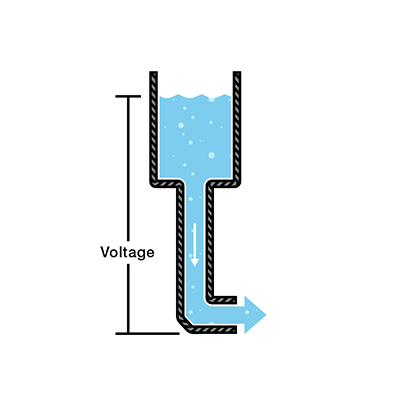
Consider
a water tank at a certain height above the ground. At the bottom of this tank
there is a hose.

The
pressure at the end of the hose can represent voltage. The water in the tank
represents charge. The more water in the tank, the higher the charge, the more
pressure is measured at the end of the hose.
We can think
of this tank as a battery, a place where we store a certain amount of energy
and then release it. If we drain our tank a certain amount, the pressure
created at the end of the hose goes down. We can think of this as decreasing
voltage, like when a flashlight gets dimmer as the batteries run down. There is
also a decrease in the amount of water that will flow through the hose. Less
pressure means less water is flowing, which brings us to current.
Current
We can
think of the amount of water flowing through the hose from the tank as current.
The higher the pressure, the higher the flow, and vice-versa. With water, we
would measure the volume of the water flowing through the hose over a certain
period of time. With electricity, we measure the amount of charge flowing
through the circuit over a period of time. Current is measured in Amperes
(usually just referred to as “Amps”). An ampere is defined as 6.241*1018
electrons (1 Coulomb) per second passing through a point in a circuit. Amps are
represented in equations by the letter “I”.
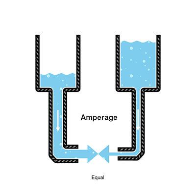
Let’s say
now that we have two tanks, each with a hose coming from the bottom. Each tank
has the exact same amount of water, but the hose on one tank is narrower than
the hose on the other.

We
measure the same amount of pressure at the end of either hose, but when the
water begins to flow, the flow rate of the water in the tank with the narrower
hose will be less than the flow rate of the water in the tank with the wider
hose. In electrical terms, the current through the narrower hose is less than
the current through the wider hose. If we want the flow to be the same through
both hoses, we have to increase the amount of water (charge) in the tank with
the narrower hose.

This
increases the pressure (voltage) at the end of the narrower hose, pushing more
water through the tank. This is analogous to an increase in voltage that causes
an increase in current.
Now we’re
starting to see the relationship between voltage and current. But there is a
third factor to be considered here: the width of the hose. In this analogy, the
width of the hose is the resistance. This means we need to add another term to
our model:
- Water = Charge (measured in Coulombs)
- Pressure = Voltage (measured in Volts)
- Flow = Current (measured in Amperes, or “Amps” for short)
- Hose Width = Resistance
Resistance
Consider
again our two water tanks, one with a narrow pipe and one with a wide pipe.

It stands
to reason that we can’t fit as much volume through a narrow pipe than a wider
one at the same pressure. This is resistance. The narrow pipe “resists” the
flow of water through it even though the water is at the same pressure as the
tank with the wider pipe.

In
electrical terms, this is represented by two circuits with equal voltages and
different resistances. The circuit with the higher resistance will allow less
charge to flow, meaning the circuit with higher resistance has less current
flowing through it.
This
brings us back to Georg Ohm. Ohm defines the unit of resistance of “1 Ohm” as
the resistance between two points in a conductor where the application of 1
volt will push 1 ampere, or 6.241×10¹⁸ electrons. This value is
usually represented in schematics with the greek letter “Ω”, which is called
omega, and pronounced “ohm”.
Ohm's Law
Combining
the elements of voltage, current, and resistance, Ohm developed the formula:

Where
- V = Voltage in volts
- I = Current in amps
- R = Resistance in ohms
This is
called Ohm’s law. Let’s say, for example, that we have a circuit with the
potential of 1 volt, a current of 1 amp, and resistance of 1 ohm. Using Ohm’s
Law we can say:

Let’s say
this represents our tank with a wide hose. The amount of water in the tank is
defined as 1 volt and the “narrowness” (resistance to flow) of the hose is
defined as 1 ohm. Using Ohms Law, this gives us a flow (current) of 1 amp.
Using
this analogy, let’s now look at the tank with the narrow hose. Because the hose
is narrower, its resistance to flow is higher. Let’s define this resistance as
2 ohms. The amount of water in the tank is the same as the other tank, so,
using Ohm’s Law, our equation for the tank with the narrow hose is

But what
is the current? Because the resistance is greater, and the voltage is the same,
this gives us a current value of 0.5 amps:


So, the
current is lower in the tank with higher resistance. Now we can see that if we
know two of the values for Ohm’s law, we can solve for the third. Let’s
demonstrate this with an experiment.
For this example, we have a 9 volt battery and a red LED with a current rating of 20 milliamps, or 0.020 amps. To be safe, we’d rather not drive the LED at its maximum current but rather its suggested current, which is listed on its datasheet as 18mA, or 0.018 amps. If we simply connect the LED directly to the battery, the values for Ohm’s law look like this:


Dividing by zero gives us infinite current! Well, not infinite in practice, but as much current as the battery can deliver. Since we do NOT want that much current flowing through our LED, we’re going to need a resistor. Our circuit should look like this:
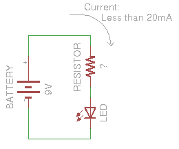
We can use Ohm’s Law in the exact same way to determine the reistor value that will give us the desired current value:


So, we need a resistor value of around 500 ohms to keep the current through the LED under the maximum current rating.
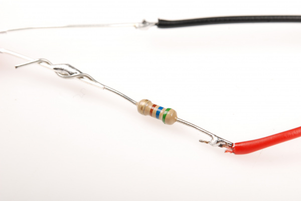
500 ohms is not a common value for off-the-shelf resistors, so this device uses a 560 ohm resistor in its place. Here’s what our device looks like all put together.
Success! We’ve chosen a resistor value that is high enough to keep the current through the LED below its maximum rating, but low enough that the current is sufficient to keep the LED nice and bright.
This LED/current-limiting resistor example is a common occurrence in hobby electronics. You’ll often need to use Ohm’s Law to change the amount of current flowing through the circuit. Another example of this implementation is seen in the LilyPad LED boards.
With this setup, instead of having to choose the resistor for the LED, the resistor is already on-board with the LED so the current-limiting is accomplished without having to add a resistor by hand.
An Ohm's Law Experiment
For this experiment, we want to use a 9 volt battery to power an LED. LEDs are fragile and can only have a certain amount of current flowing through them before they burn out. In the documentation for an LED, there will always be a “current rating”. This is the maximum amount of current that can flow through the particular LED before it burns out.Materials Required
In order to perform the experiments listed at the end of the tutorial, you will need:
- A multimeter
- A 9-Volt battery
- A 560-Ohm resistor(or the next closest value)
- An LED
For this example, we have a 9 volt battery and a red LED with a current rating of 20 milliamps, or 0.020 amps. To be safe, we’d rather not drive the LED at its maximum current but rather its suggested current, which is listed on its datasheet as 18mA, or 0.018 amps. If we simply connect the LED directly to the battery, the values for Ohm’s law look like this:
therefore:
and since we have no resistance yet:
Dividing by zero gives us infinite current! Well, not infinite in practice, but as much current as the battery can deliver. Since we do NOT want that much current flowing through our LED, we’re going to need a resistor. Our circuit should look like this:
We can use Ohm’s Law in the exact same way to determine the reistor value that will give us the desired current value:
therefore:
plugging in our values:
solving for resistance:
So, we need a resistor value of around 500 ohms to keep the current through the LED under the maximum current rating.
500 ohms is not a common value for off-the-shelf resistors, so this device uses a 560 ohm resistor in its place. Here’s what our device looks like all put together.
Success! We’ve chosen a resistor value that is high enough to keep the current through the LED below its maximum rating, but low enough that the current is sufficient to keep the LED nice and bright.
This LED/current-limiting resistor example is a common occurrence in hobby electronics. You’ll often need to use Ohm’s Law to change the amount of current flowing through the circuit. Another example of this implementation is seen in the LilyPad LED boards.
With this setup, instead of having to choose the resistor for the LED, the resistor is already on-board with the LED so the current-limiting is accomplished without having to add a resistor by hand.


0 comments:
Post a Comment