Normal Diodes
Standard signal diodes are among the most basic, average, no-frills members of the diode family. They usually have a medium-high forward voltage drop and a low maximum current rating. A common example of a signal diode is the 1N4148. Very general purpose, it’s got a typical forward voltage drop of 0.72V and a 300mA maximum forward current rating.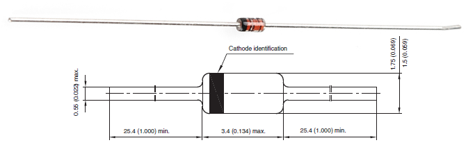
A small-signal diode, the 1N4148. Notice the black circle around the diode, that marks which of the terminals is the cathode.
A rectifier or power diode is a standard diode with a
much higher maximum current rating. This higher current rating usually
comes at the cost of a larger forward voltage. The 1N4001, for example, has a current rating of 1A and a forward voltage of 1.1V.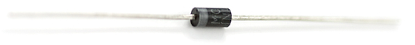
A 1N4001 PTH diode. This time a gray band indicates which pin is the cathode.
And, of course, most diode types come in surface-mount varieties as
well. You’ll notice that every diode has some way (no matter how tiny or
hard to see) to indicate which of the two pins is the cathode.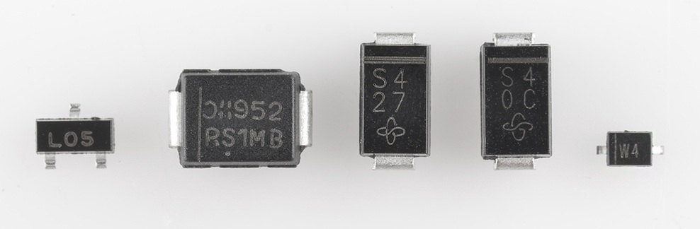
Light-Emitting Diodes (LEDs!)
The flashiest member of the diode family must be the light-emitting diode (LED). These diodes quite literally light up when a positive voltage is applied.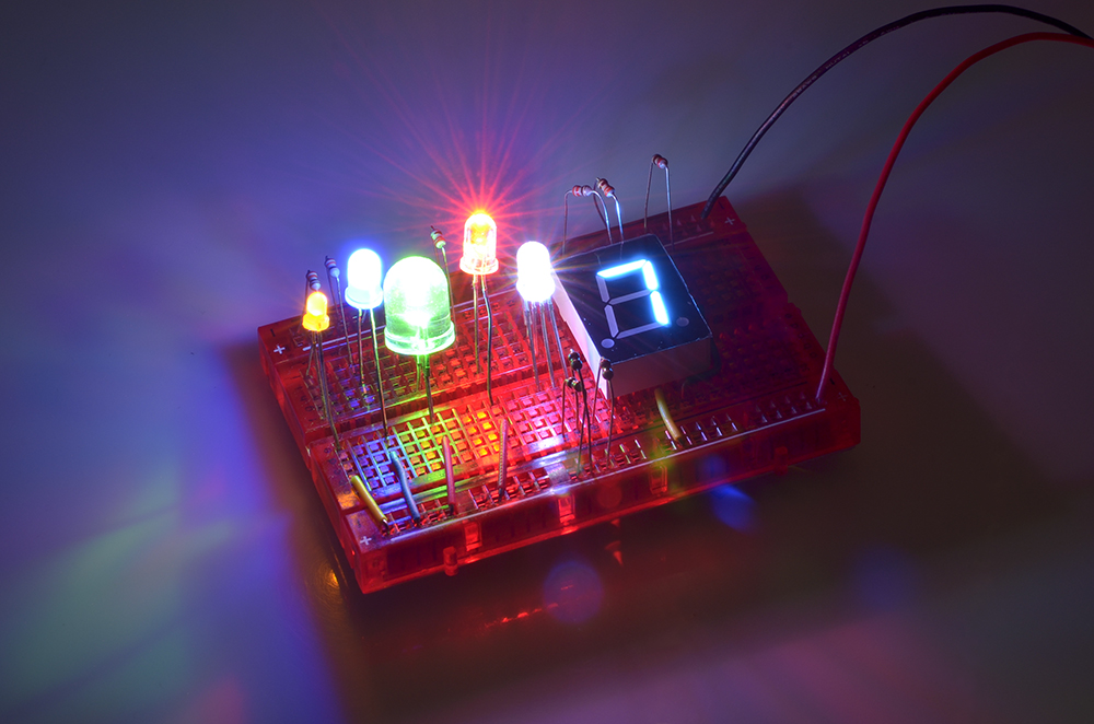
A handful of through-hole LEDs. From left to right: a yellow 3mm, blue 5mm, green 10mm, super-bright red 5mm, an RGB 5mm and a blue 7-segment LED.
Like normal diodes, LEDs only allow current through one direction.
They also have a forward voltage rating, which is the voltage required
for them to light up. The VF rating of an LED is usually
larger than that of a normal diode (1.2~3V), and it depends on the color
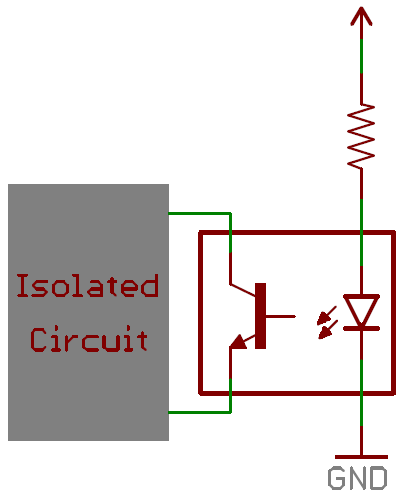
the LED emits. For example, the rated forward voltage of a Super Bright Blue LED is around 3.3V, while that of the equal size Super Bright Red LED is only 2.2V.You’ll obviously most-often find LEDs in lighting applications. They’re blinky and fun! But more than that, their high-efficiency has lead to widespread use in street lights, displays, backlighting, and much more. Other LEDs emit a light that is not visible to the human eye, like infrared LEDs, which are the backbone of most remote controls. Another common use of LEDs is in optically isolating a dangerous high-voltage system from a lower-voltage circuit. Opto-isolators pair an infrared LED with a photosensor, which allows current to flow when it detects light from the LED. Below is an example circuit of an opto-isolator. Note how the schematic symbol for the diode varies from the normal diode. LED symbols add a couple arrows extending out from the symbol.
Schottky Diodes
Another very common diode is the Schottky diode. The semiconductor composition of a Schottky diode is slightly different from a normal diode, and this results in a much smaller forward voltage drop, which is usually between 0.15V and 0.45V. They’ll still have a very large breakdown voltage though.Schottky diodes are especially useful in limiting losses, when every last bit of voltage must be spared. They’re unique enough to get a circuit symbol of their own, with a couple bends on the end of the cathode-line.

Zener Diodes
Zener diodes are the weird outcast of the diode family. They’re usually used to intentionally conduct reverse current. Zener’s are designed to have a very precise breakdown voltage, called the zener breakdown or zener voltage. When enough current runs in reverse through the zener, the voltage drop across it will hold steady at the breakdown voltage.Taking advantage of their breakdown property, Zener diodes are often used to create a known reference voltage at exactly their Zener voltage. They can be used as a voltage regulator for small loads, but they’re not really made to regulate voltage to circuits that will pull significant amounts of current.
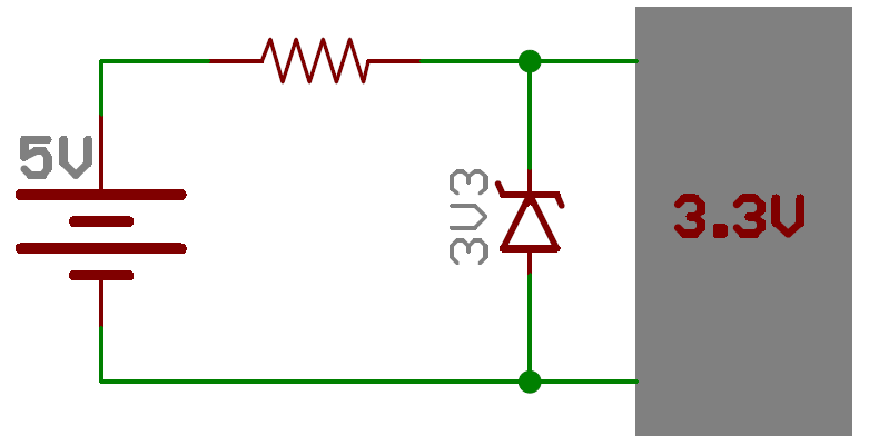
Zeners are special enough to get their own circuit symbol, with wavy ends on the cathode-line. The symbol might even define what, exactly, the diode’s zener voltage is. Here’s a 3.3V zener diode acting to create a solid 3.3V voltage reference:
Photodiodes
Photodiodes are specially constructed diodes, which capture energy from photons of light (see Physics, quantum) to generate electrical current. Kind of operating as an anti-LED.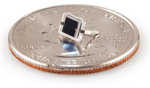
A BPW34 photodiode (not the quarter,
the little thing on top of that). Get it under the sun and it can
generate about few µW’s of power!.
Solar cells are the main benefactor of photodiode technology. But
these diodes can also be used to detect light, or even communicate
optically.Diode Applications
For such a simple component, diodes have a huge range of uses. You’ll find a diode of some type in just about every circuit. They could be featured in anything from a small-signal digital logic to a high voltage power conversion circuit. Let’s explore some of these applications.Rectifiers
A rectifier is a circuit that converts alternating current (AC) to direct current (DC). This conversion is critical for all sorts of household electronics. AC signals come out of your house’s wall outlets, but DC is what powers most computers and other microelectronics.Current in AC circuits literally alternates – quickly switches between running in the positive and negative directions – but current in a DC signal only runs in one direction. So to convert from AC to DC you just need to make sure current can’t run in the negative direction. Sounds like a job for DIODES!
A half-wave rectifier can be made out of just a single diode. If an AC signal, like a sine wave for example, is sent through a diode any negative component to the signal is clipped out.
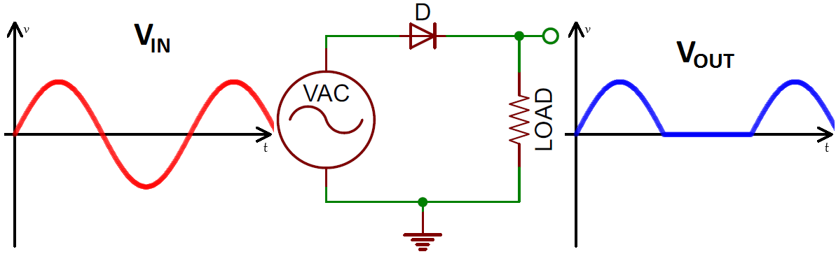
Input (red/left) and output (blue/right) voltage waveforms, after passing through the half-wave rectifier circuit (middle).
A full-wave bridge rectifier uses four diodes to convert those negative humps in the AC signal into positive humps.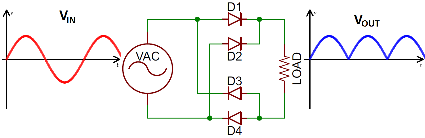
The bridge rectifier circuit (middle), and the output wave form it creates (blue/right).
These circuits are a critical component in AC-to-DC power supplies,
which turn the wall outlet’s 120/240VAC signal into 3.3V, 5V, 12V, etc.
DC signals. If you tore apart a wall-wart, you’d most likely see a handful of diodes in there, rectifying it up.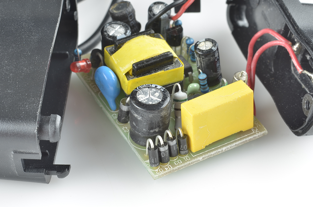
Can you spot the four diodes making a bridge rectifier in this wall-wart?
Reverse Current Protection
Ever stick a battery in the wrong way? Or switch up the red and black power wires? If so, a diode might be to thank for your circuit still being alive. A diode placed in series with the positive side of the power supply is called a reverse protection diode. It ensures that current can only flow in the positive direction, and the power supply only applies a positive voltage to your circuit.
The drawback of a reverse protection diode is that it’ll induce some voltage loss because of the forward voltage drop. This makes Schottky diodes an excellent choice for reverse protection diodes.
Logic Gates
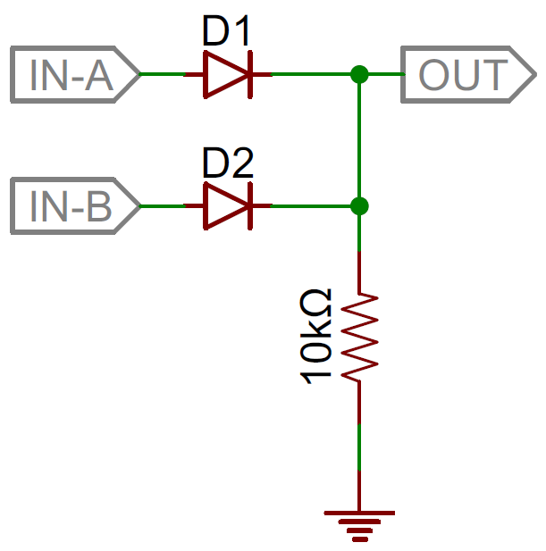
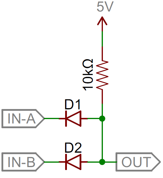
Forget transistors! Simple digital logic gates, like the AND or the OR, can be built out of diodes.For example, a diode two-input OR gate can be constructed out of two diodes with shared cathode nodes. The output of the logic circuit is also located at that node. Whenever either input (or both) is a logic 1 (high/5V) the output becomes a logic 1 as well. When both inputs are a logic 0 (low/0V), the output is pulled low through the resistor.
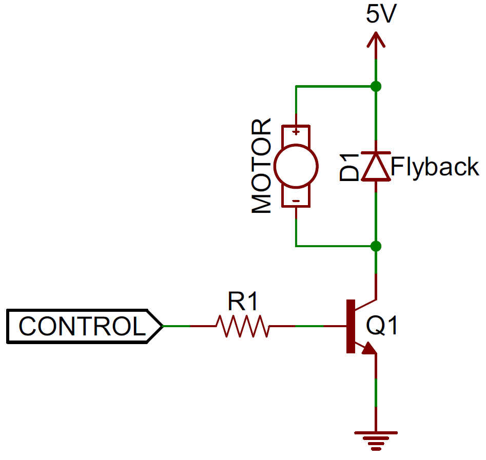
Flyback Diodes and Voltage Spike Suppression
Diodes are very often used to limit potential damage from unexpected large spikes in voltage. Transient-voltage-suppression (TVS) diodes are specialty diodes, kind of like zener diodes – lowish breakdown voltages (often around 20V) – but with very large power ratings (often in the range of kilowatts). They’re designed to shunt currents and absorb energy when voltages exceed their breakdown voltage.Flyback diodes do a similar job of suppressing voltage spikes, specifically those induced by an inductive component, like a motor. When current through an inductor suddenly changes, a voltage spike is created, possibly a very large, negative spike. A flyback diode placed across the inductive load, will give that negative voltage signal a safe path to discharge, actually looping over-and-over through the inductor and diode until it eventually dies out.


0 comments:
Post a Comment