Introduction
Once you graduate from the simple, passive components that are resistors, capacitors, and inductors, it’s time to step on up to the wonderful world of semiconductors. One of the most widely used semiconductor components is the diode.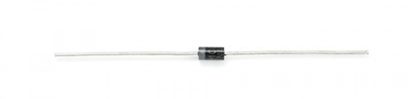
- What is a diode!?
- Theory of diode operation
- Important diode properties
- Different types of diodes
- What diodes look like
- Typical diode applications
Ideal Diodes
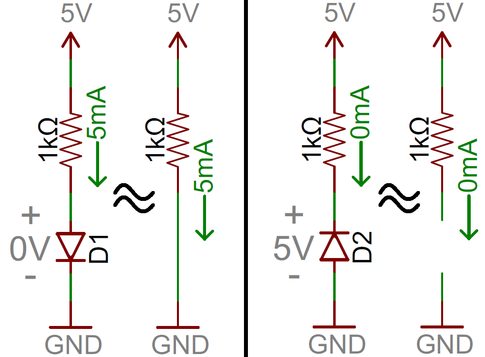
The key function of an ideal diode is to control the direction of current-flow. Current passing through a diode can only go in one direction, called the forward direction. Current trying to flow the reverse direction is blocked. They’re like the one-way valve of electronics.If the voltage across a diode is negative, no current can flow*, and the ideal diode looks like an open circuit. In such a situation, the diode is said to be off or reverse biased.
As long as the voltage across the diode isn’t negative, it’ll “turn on” and conduct current. Ideally* a diode would act like a short circuit (0V across it) if it was conducting current. When a diode is conducting current it’s forward biased (electronics jargon for “on”).
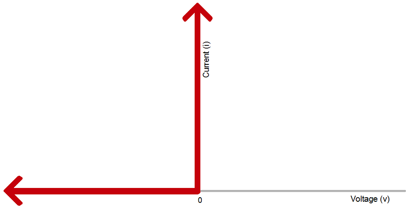
The current-voltage relationship of
an ideal diode. Any negative voltage produces zero current – an open
circuit. As long as the voltage is non-negative the diode looks like a
short circuit.
| Ideal Diode Characteristics | ||
| Operation Mode | On (Forward biased) | Off (Reverse biased) |
|---|---|---|
| Current Through | I>0 | I=0 |
| Voltage Across | V=0 | V<0 |
| Diode looks like | Short circuit | Open circuit |
Circuit Symbol
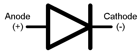
Every diode has two terminals – connections on each end of the component – and those terminals are polarized, meaning the two terminals are distinctly different. It’s important not to mix the connections on a diode up. The positive end of a diode is called the anode, and the negative end is called the cathode. Current can flow from the anode end to the cathode, but not the other direction. If you forget which way current flows through a diode, try to remember the mnemonic ACID: “anode current in diode” (also anode cathode is diode).The circuit symbol of a standard diode is a triangle butting up against a line. As we’ll cover in the later in this tutorial, there are a variety of diode types, but usually their circuit symbol will look something like this:
*Caveat! Asterisk! Not-entirely-true… Unfortunately, there’s no such thing as an ideal diode. But don’t worry! Diodes really are real, they’ve just got a few characteristics which make them operate as a little less than our ideal model…
Real Diode Characteristics
Ideally, diodes will block any and all current flowing the reverse direction, or just act like a short-circuit if current flow is forward. Unfortunately, actual diode behavior isn’t quite ideal. Diodes do consume some amount of power when conducting forward current, and they won’t block out all reverse current. Real-world diodes are a bit more complicated, and they all have unique characteristics which define how they actually operate.Current-Voltage Relationship
The most important diode characteristic is its current-voltage (i-v) relationship. This defines what the current running through a component is, given what voltage is measured across it. Resistors, for example, have a simple, linear i-v relationship…Ohm’s Law. The i-v curve of a diode, though, is entirely non-linear. It looks something like this: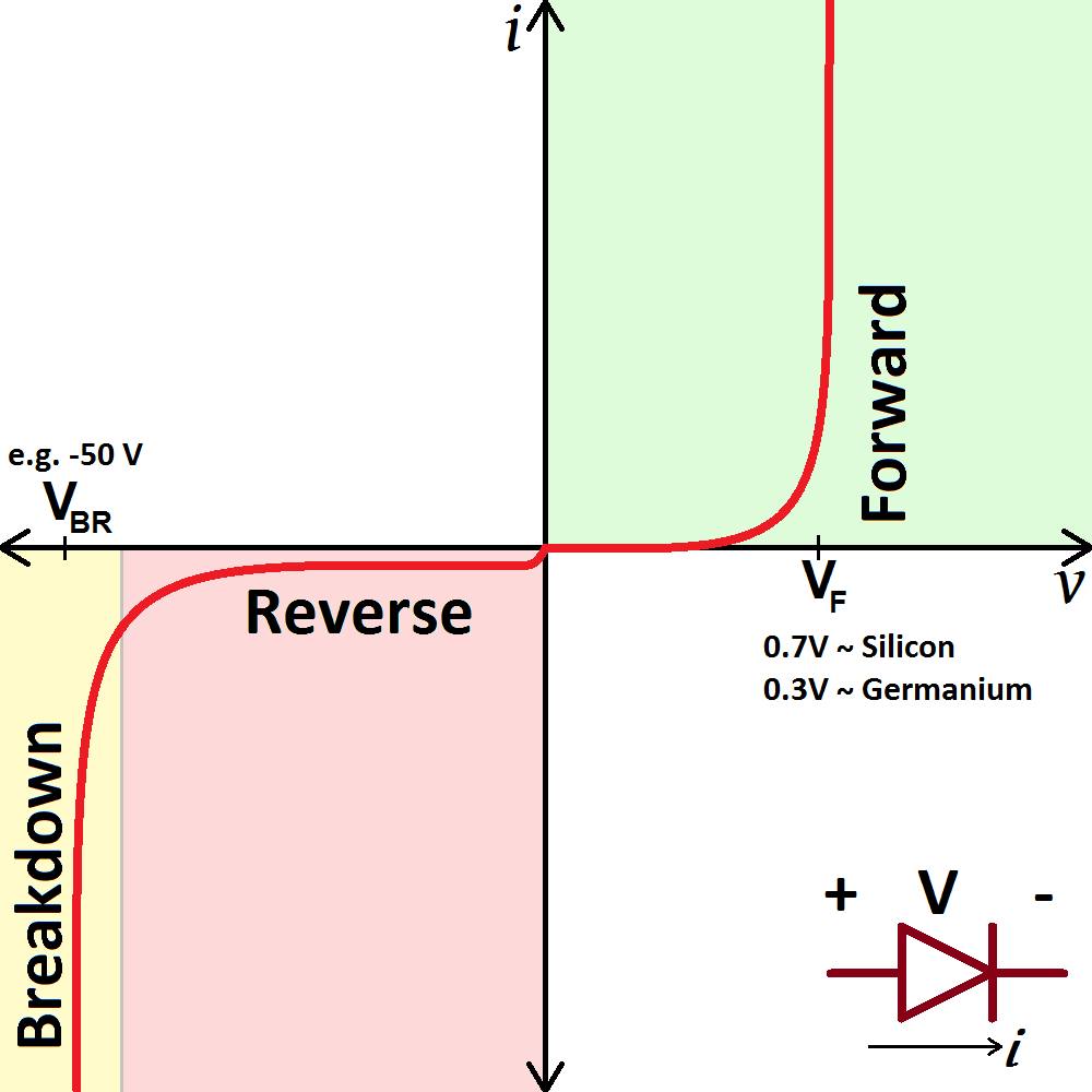
The current-voltage relationship of a
diode. In order to exaggerate a few important points on the plot, the
scales in both the positive and negative halves are not equal.
Depending on the voltage applied across it, a diode will operate in one of three regions:- Forward bias: When the voltage across the diode is positive the diode is “on” and current can run through. The voltage should be greater than the forward voltage (VF) in order for the current to be anything significant.
- Reverse bias: This is the “off” mode of the diode, where the voltage is less than VF but greater than -VBR. In this mode current flow is (mostly) blocked, and the diode is off. A very small amount of current (on the order of nA) – called reverse saturation current – is able to flow in reverse through the diode.
- Breakdown: When the voltage applied across the diode is very large and negative, lots of current will be able to flow in the reverse direction, from cathode to anode.
Forward Voltage
In order to “turn on” and conduct current in the forward direction, a diode requires a certain amount of positive voltage to be applied across it. The typical voltage required to turn the diode on is called the forward voltage (VF). It might also be called either the cut-in voltage or on-voltage.As we know from the i-v curve, the current through and voltage across a diode are interdependent. More current means more voltage, less voltage means less current. Once the voltage gets to about the forward voltage rating, though, large increases in current should still only mean a very small increase in voltage. If a diode is fully conducting, it can usually be assumed that the voltage across it is the forward voltage rating.
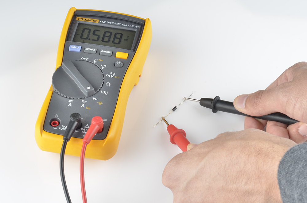
A multimeter with a diode setting can be used to measure (the minimum of) a diode’s forward voltage drop.
A specific diode’s VF depends on what semiconductor material it’s made out of. Typically, a silicon diode will have a VF around 0.6-1V. A germanium-based diode might be lower, around 0.3V. The type of diode also has some importance in defining the forward voltage drop; light-emitting diodes can have a much larger VF, while Schottky diodes are designed specifically to have a much lower-than-usual forward voltage.Breakdown Voltage
If a large enough negative voltage is applied to the diode, it will give in and allow current to flow in the reverse direction. This large negative voltage is called the breakdown voltage. Some diodes are actually designed to operate in the breakdown region, but for most normal diodes it’s not very healthy for them to be subjected to large negative voltages.For normal diodes this breakdown voltage is around -50V to -100V, or even more negative.
Diode Datasheets
All of the above characteristics should be detailed in the datasheet for every diode. For example, this datasheet for a 1N4148 diode lists the maximum forward voltage (1V) and the breakdown voltage (100V) (among a lot of other information):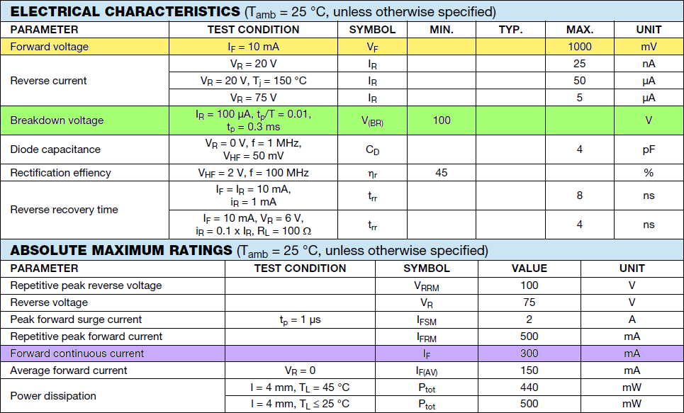
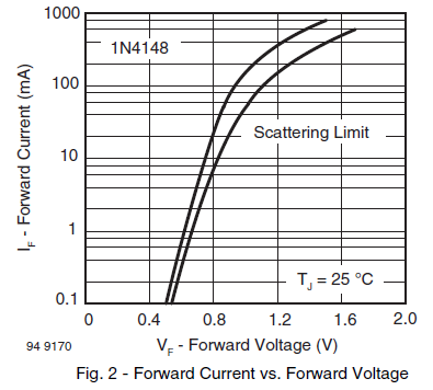
Some diodes are well-suited to high currents – 1A or more – others like the 1N4148 small-signal diode shown above may only be suited for around 200mA.
That 1N4148 is just a tiny sampling of all the different kinds of diodes there are out there. Next we’ll explore what an amazing variety of diodes there are and what purpose each type serves.


0 comments:
Post a Comment