PCB
Electronic circuits in schools and industry are
normally manufactured through the use of PCBs (Printed Circuit Boards).
The boards are made from glass reinforced plastic with copper tracks in
the place of wires. Components are fixed in position by drilling
holes through the board, locating the components and then soldering them
in place. The copper tracks link the components together
forming a circuit.

The two diagrams below show the track side of a PCB (normally the
underneath side) and the component side (normally the top side) of the
same circuit. The relay and integrated circuit are ready to be placed in
position and soldered.
|
||
 |
||
|
|
||
 |
A circuit such as the one shown opposite can be drawn
using software such as ‘Crocodile Technology®’ (now known as Yenka
Electronics). This allows individual
components such as resistors, integrated circuits and capacitors to be
dragged onto the screen and connected together, forming a complete
circuit. The finished circuit can then be simulated on screen. If the
circuit is not correct it can be altered until it works in the desired
way.
This allows you to test the circuit on the computer and correct any mistakes or make improvements. This saves time as there is no need to build the circuit with real components. |
|
 |
Circuits can also be built on a breadboard using real components. This
is a time consuming method and often mistakes occur as many components
are small and it is easy to connect components incorrectly, causing a
circuit to fail. Also, breadboards are prone to damage as the small
connections on the boards are quite delicate. Using simulation software such as Crocodile Technology® is recommended as it is a much more reliable and accurate method of testing a circuit. | |
Tuesday, September 1, 2015
3:45 AM
No comments
3:02 AM
No comments
Overview
Welcome to circuits One of the first things you’ll encounter when learning about electronics is the concept of a circuit. This tutorial will explain what a circuit is, as well as discuss voltage in further detail.
A simple circuit, involving a button, an LED, and a resistor, built two different ways.
Circuit Basics
Volatage and How it Works
You’ve probably heard that a battery or a wall outlet has a certain number of volts. This is a measurement of the electrical potential produced by the battery, or the utility grid connected to the wall outlet.All those volts are sitting there waiting for you to use them, but there’s a catch: in order for electricity to do any work, it needs to be able to move. It’s kind of like a blown-up balloon; if you pinch it off, there is air in there that could do something if it’s released, but it won’t actually do anything until you let it out.
Unlike air coming out of a balloon, electricity can only flow through materials that can conduct electricity, such as copper wire. If you connect a wire to a battery or wall outlet (WARNING: the voltage in a wall outlet is dangerous, don’t do this!), you will be giving the electricity a path to follow. But if the wire isn’t connected to anything else, the electricity won’t have anywhere to go and still won’t move.


Why does every source of electricity have two sides? This goes back to the idea of “potential”, and that you need a voltage difference in order to get electricity to flow. It sounds silly, but you can’t have a difference without two things to be different. In any power supply, the positive side will have a higher voltage than the negative side, which is exactly what we want. In fact, when we measure voltage, we usually say that the negative side is 0 volts, and the positive side is however many volts the supply can provide.
Electrical sources are like pumps. Pumps always have two sides, an outlet that blows something out, and an inlet that sucks something in. Batteries and generators and solar panels work the same way. Something inside them is hard at work moving electricity towards the outlet (the positive side), but all that electricity leaving the device creates a void, which means that the negative side needs to pull electricity in to replace it.*
What have we learned so far?
- Voltage is potential, but electricity needs to flow to do anything useful.
- Electricity needs a path to flow through, which must be an electrical conductor such as copper wire.
- Electricity will flow from a higher voltage to a lower voltage.
- DC voltage sources always have two sides, called positive and negative, with the positive side a higher voltage than the negative side.
The Simplest Circuit
We’re finally ready to make electricity work for us! If we connect the positive side of a voltage source, through something that does some work such as a Light Emitting Diode (LED), and back to the negative side of the voltage source; electricity, or current, will flow. And we can put things in the path that do useful things when current flows through them, like LEDs that light up.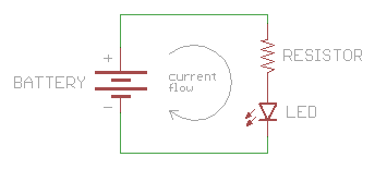
Click this link to see a simulation of current flowing through a simple circuit. This simulation requires Java to run.
*Benjamin Franklin originally wrote that electricity flows from the positive side of a voltage source to the negative side. However, Franklin had no way of knowing that electrons actually flow in the opposite direction - at the atomic level, they come out of the negative side and loop back to the positive side. Because engineers followed Franklin’s lead for hundreds of years before the truth was discovered, we still use the “wrong” convention to this day. Practically speaking this detail doesn’t matter, and as long as everyone uses the same convention, we can all build circuits that work just fine.
Short and Open Circuits
What is a “Load”?
The reason we want to build circuits is to make electricity do useful things for us. The way we do that is by putting things in the circuit that use the current flow to light up, make noise, run programs, etc.These things are called loads, because they “load down” the power supply, just like you’re “loaded down” when you’re carrying something. The same way you could be loaded down with too much weight, it’s possible to load down a power supply too much, which will slow down the current flow. But unlike you, it’s also possible to load down a circuit too little - this may let too much current flow (imagine running too fast if you weren’t carrying any weight), which can burn out your parts or even the power supply.
You’ll learn all about voltage, current, and loads in the next tutorial: Voltage, Current, Resistance, and Ohm’s Law. But for now, let’s learn about two special cases of circuit: short circuit, and open circuit. Knowing about these will help tremendously when you’re troubleshooting your own circuits.
Short Circuit
DON’T DO THIS, but if you connect a wire directly from the positive to the negative side of a power supply, you’ll create what is called a short circuit. This is a very bad idea.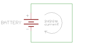
If you DO have a load in the current, the current flow through your circuit will be limited to that which your device consumes, which is usually a very small amount. However, if you DON’T put anything in to restrict the current flow, there won’t be anything to slow down the current, and it will try to be infinite!
Your power supply can’t provide infinite current, but it will provide as much as it can, which may be a lot. This could cause your wire to burn up, damage the power supply, drain your battery, or other exciting things. Most of the time your power supply will have some sort of safety mechanism built into it to limit the maximum current in the event of a short circuit, but not always. This is the reason all homes and buildings have circuit breakers, to prevent fires from starting in the event of a short circuit somewhere in the wiring.
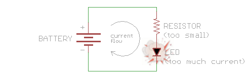
A closely related problem is accidentally letting too much current flow through part of your circuit, causing a part to burn up. This isn’t quite a short circuit, but it’s close. This most often happens when you use the incorrect resistor value, which lets too much current flow through another component such as an LED.
Open Circuit
The opposite of a short circuit is an open circuit. This is a circuit where the loop isn’t fully connected (and therefore this isn’t really a circuit at all).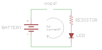
If your circuit doesn’t work, the most likely cause is an open circuit. This is usually due to a broken connection or a loose wire. (Short circuits can steal all the power from the rest of your circuit, so be sure to look for those as well.)
TIP: if you can’t easily find where your circuit is open, a multimeter can be very useful tool. If you set it to measure volts, you can use it to check the voltage at various points in your powered circuit, and eventually find the point where voltage isn’t getting through.
2:43 AM
No comments
Introduction
Integrated circuits (ICs) are a keystone of modern electronics. They are the heart and brains of most circuits. They are the ubiquitous little black “chips” you find on just about every circuit board. Unless you’re some kind of crazy, analog electronics wizard, you’re likely to have at least one IC in every electronics project you build, so it’s important to understand them, inside and out.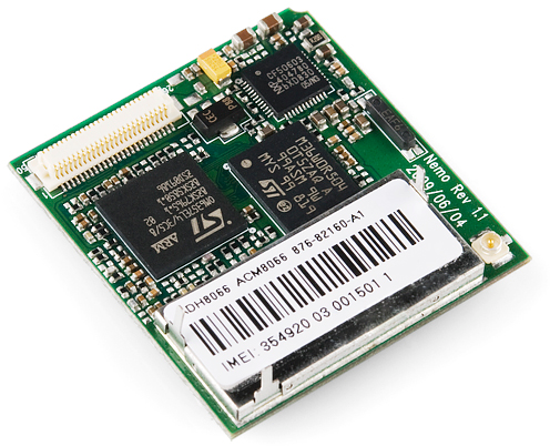
Integrated circuits are the little black “chips”, found all over embedded electronics.
An IC is a collection of electronic components – resistors, transistors, capacitors,
etc. – all stuffed into a tiny chip, and connected together to achieve a
common goal. They come in all sorts of flavors: single-circuit logic
gates, op amps, 555 timers, voltage regulators, motor controllers,
microcontrollers, microprocessors, FPGAs…the list just goes on-and-on.Covered in this Tutorial
- The make-up of an IC
- Common IC packages
- Identifying ICs
- Commonly used ICs
Inside the IC
When we think integrated circuits, little black chips are what come to mind. But what’s inside that black box?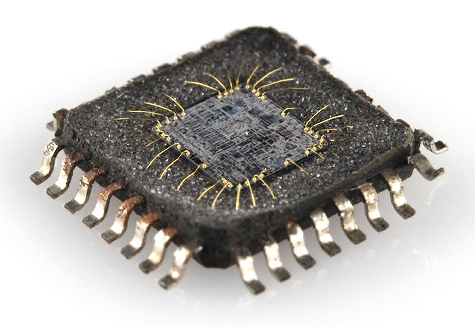
The guts of an integrated circuit, visible after removing the top.
The real “meat” to an IC is a complex layering of semiconductor
wafers, copper, and other materials, which interconnect to form
transistors, resistors or other components in a circuit. The cut and
formed combination of these wafers is called a die.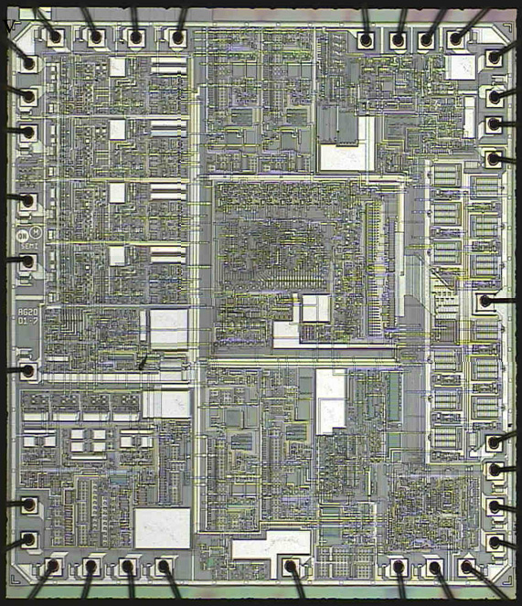
An overview of an IC die.
While the IC itself is tiny, the wafers of semiconductor and layers
of copper it consists of are incredibly thin. The connections between
the layers are very intricate. Here’s a zoomed in section of the die
above: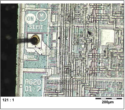
IC Packages
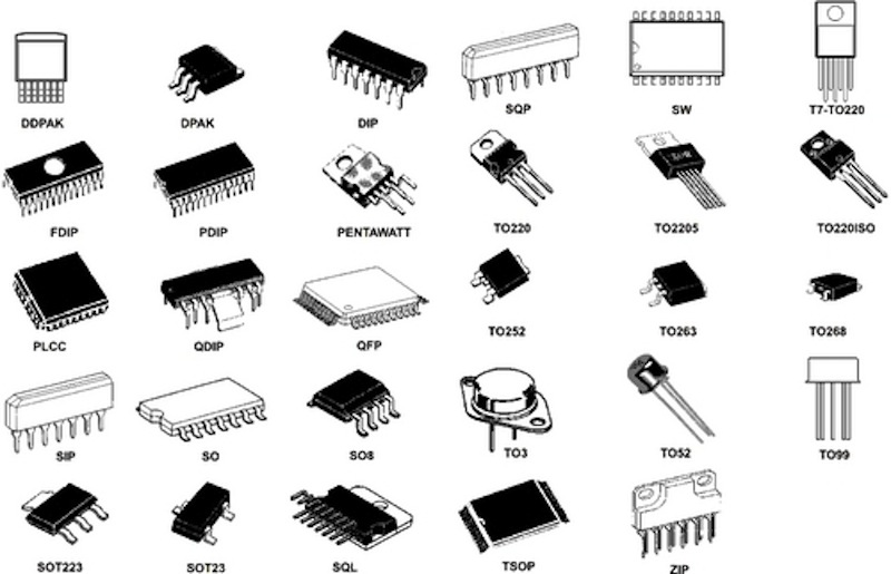
The package is what encapsulates the integrated circuit die and splays it out into a device we can more easily connect to. Each outer connection on the die is connected via a tiny piece of gold wire to a pad or pin on the package. Pins are the silver, extruding terminals on an IC, which go on to connect to other parts of a circuit. These are of utmost importance to us, because they’re what will go on to connect to the rest of the components and wires in a circuit.There are many different types of packages, each of which has unique dimensions, mounting-types, and/or pin-counts.
Polarity Marking and Pin Numbering
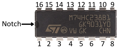
All ICs are polarized, and every pin is unique in terms of both location and function. This means the package has to have some way to convey which pin is which. Most ICs will use either a notch or a dot to indicate which pin is the first pin. (Sometimes both, sometimes one or the other.)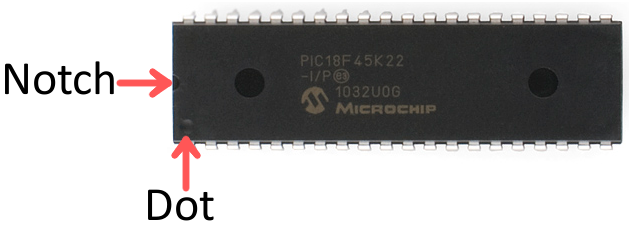
Mounting Style
One of the main distinguishing package type characteristics is the way they mount to a circuit board. All packages fall into one of two mounting types: through-hole (PTH) or surface-mount (SMD or SMT). Through-hole packages are generally bigger, and much easier to work with. They’re designed to be stuck through one side of a board and soldered to the other side.Surface-mount packages range in size from small to minuscule. They are all designed to sit on one side of a circuit board and be soldered to the surface. The pins of a SMD package either extrude out the side, perpendicular to the chip, or are sometimes arranged in a matrix on the bottom of the chip. ICs in this form factor are not very “hand-assembly-friendly.” They usually require special tools to aid in the process.
DIP (Dual in-line packages)
DIP, short for dual in-line package, is the most common through-hole IC package you’ll encounter. These little chips have two parallel rows of pins extending perpendicularly out of a rectangular, black, plastic housing.
The 28-pin ATmega328 is one of the more popular DIP-packaged microcontrollers (thanks, Arduino!).
Each of the pins on a DIP IC are spaced by 0.1" (2.54mm), which is a standard spacing and perfect for fitting into breadboards
and other prototyping boards. The overall dimensions of a DIP package
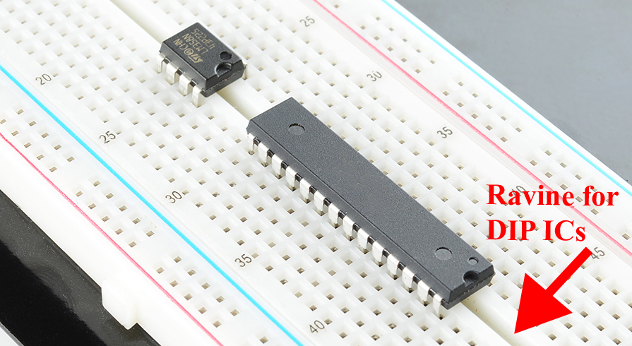
depend on its pin count, which may be anywhere from four to 64.The area between each row of pins is perfectly spaced to allow DIP ICs to straddle the center area of a breadboard. This provides each of the pins its own row in the board, and it makes sure they don’t short to each other.
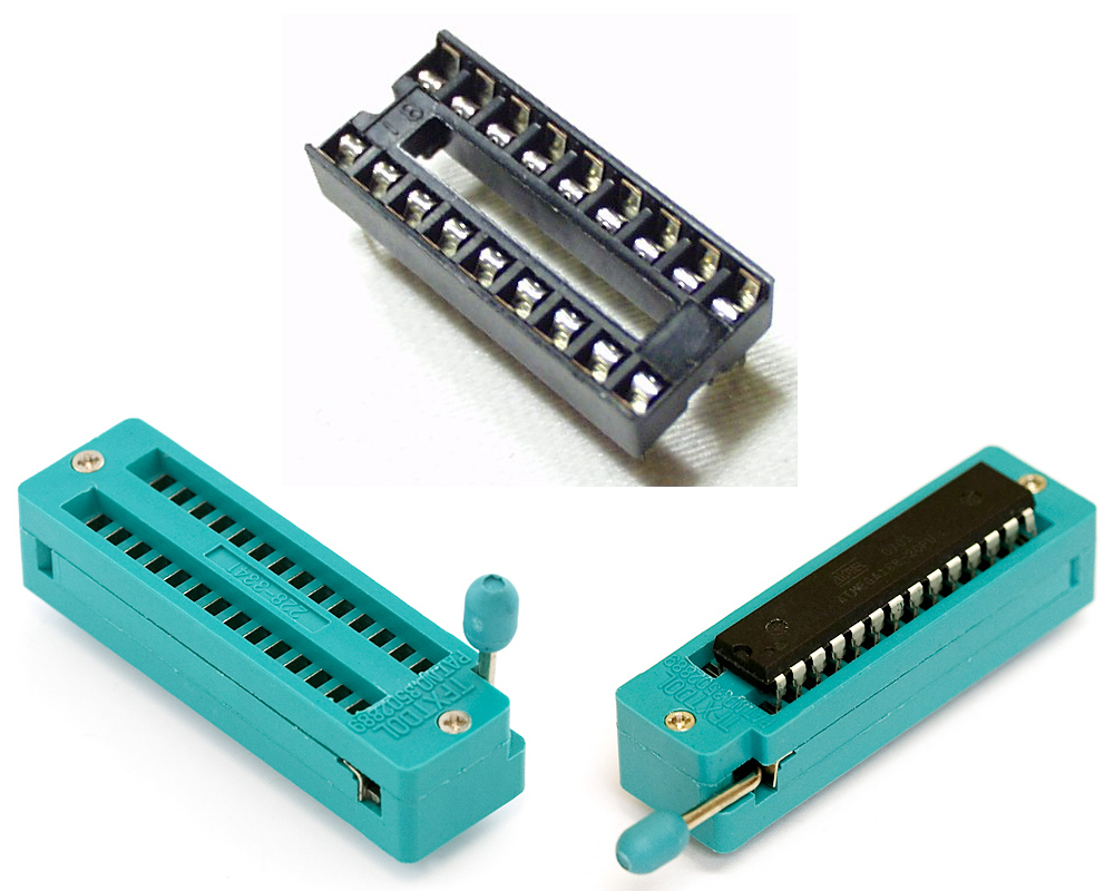
A regular DIP socket (top) and a ZIF socket with and without an IC.
Surface-Mount (SMD/SMT) Packages
There is a huge variety of surface-mount package types these days. In order to work with surface-mount packaged ICs, you usually need a custom printed circuit board (PCB) made for them, which has a matching pattern of copper on which they’re soldered.Here are a few of the more common SMD package types out there, ranging in hand-solderability from “doable” to “doable, but only with special tools” to “doable only with very special, usually automated tools”.
Small-Outline (SOP)
Small-outline IC (SOIC) packages are the surface-mount cousin of the DIP. It’s what you’d get if you bent all the pins on a DIP outward, and shrunk it down to size. With a steady hand, and a close eye, these packages are among the easiest SMD parts to hand solder. On SOIC packages, each pin is usually spaced by about 0.05" (1.27mm) from the next.The SSOP (shrink small-outline package) is an even smaller version of SOIC packages. Other, similar IC packages include TSOP (thin small-outline package) and TSSOP (thin-shrink small-outline package).

A 16-Channel Multiplexer (CD74HC4067) in a 24-pin SSOP package. Mounted on a board in the middle (quarter added for size-comparison).
A lot of the more simple, single-task-oriented ICs like the MAX232 or multiplexers come in SOIC or SSOP forms.Quad Flat Packages
Splaying IC pins out in all four directions gets you something that might look like a quad flat package (QFP). QFP ICs might have anywhere from eight pins per side (32 total) to upwards of seventy (300+ total). The pins on a QFP IC are usually spaced by anywhere from 0.4mm to 1mm. Smaller variants of the standard QFP package include thin (TQFP), very thin (VQFP), and low-profile (LQFP) packages.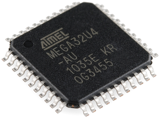
The ATmega32U4 in a 44-pin (11 on each side) TQFP package.
If you sanded the legs off a QFP IC, you get something that might look like a quad-flat no-leads (QFN)
package. The connections on QFN packages are tiny, exposed pads on the
bottom corner edges of the IC. Sometimes they wrap around, and are
exposed on both the side and bottom, other packages only expose the pad
on the bottom of the chip.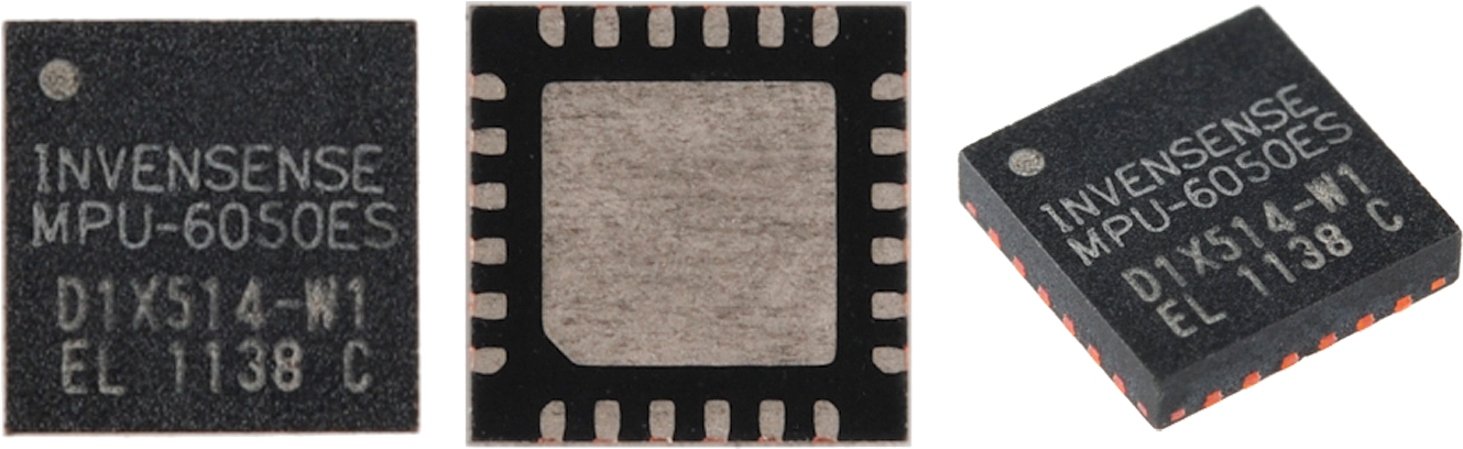
The multitalented MPU-6050 IMU sensor comes in a relatively tiny QFN package, with 24 total pins hiding on the bottom edge of the IC.
Thin (TQFN), very thin (VQFN), and micro-lead (MLF) packages are
smaller variations of the standard QFN package. There are even dual
no-lead (DFN) and thin-dual no-lead (TDFN) packages, which have pins on
just two of the sides.Many microprocessors, sensors, and other modern ICs come in QFP or QFN packages. The popular ATmega328 microcontroller is offered in both a TQFP package and a QFN-type (MLF) form, while a tiny accelerometer/gyroscope like the MPU-6050 comes in a miniscule QFN form.
Ball Grid Arrays
Finally, for really advanced ICs, there are ball grid array (BGA) packages. These are amazingly intricate little packages where little balls of solder are arranged in a 2-D grid on the bottom of the IC. Sometimes the solder balls are attached directly to the die!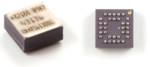
If you can hand solder a BGA-packaged IC, consider yourself a master solderer. Usually, to put these packages onto a PCB requires an automated procedure involving pick-and-place machines and reflow ovens.
Common ICs
Integrated circuits are prevalent in so many forms across electronics, it’s hard to cover everything. Here are a few of the more common ICs you might encounter in educational electronics.Logic Gates, Timers, Shift Registers, Etc.
Logic gates, the building blocks of much more ICs themselves, can be packaged into their own integrated circuit. Some logic gate ICs might contain a handful of gates in one package, like this quad-input AND gate: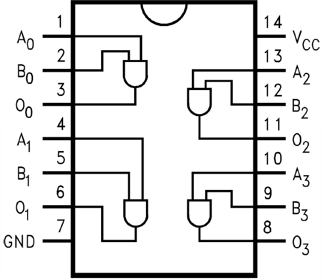
Microcontrollers, Microprocessors, FPGAs, Etc.
Microcontrollers, microprocessors, and FPGAs, all packing thousands, millions, even billions of transistors into a tiny chip, are all integrated circuits. These components exist in a wide range in functionality, complexity, and size; from an 8-bit microcontroller like the ATmega328 in an Arduino, to a complex 64-bit, multi-core microprocessor organizing activity in your computer.These components are usually the largest IC in a circuit. Simple microcontrollers can be found in packages ranging from DIP to QFN/QFP, with pin counts lying somewhere between eight and a hundred. As these components grow in complexity, the package gets equally complex. FPGAs and complex microprocessors can have upwards of a thousand pins and are only available in advanced packages like QFN, LGA, or BGA.
Sensors
Modern digital sensors, like temperature sensors, accelerometers, and gyroscopes all come packed into an integrated circuit.These ICs are usually smaller than the microcontrollers, or other ICs on a circuit board, with pin counts in the three to twenty range. DIP sensor ICs are becoming a rarity, as modern components are usually found in QFP, QFN, even BGA packages.
2:29 AM
1 comment
The thyristor or silicon controlled rectifier, SCR is a device that is widely used for controlling or switching power and often high voltage AC or DC circuits.

Thyristors are able to switch large levels of power are accordingly they used in a wide variety of different applications. Thyristors even finds uses in low power electronics where they are used in many circuits from light dimmers to power supply over voltage protection.
The term SCR or silicon controlled rectifier is often used synonymously with that of thyristor - the SCR or silicon controlled rectifier is actually a trade name used by General Electric.
SCR discovery
The idea for the thyristor was first described by Shockley in 1950. It was referred to as a bipolar transistor with a p-n hook-collector. The mechanism for the operation was analysed further in 1952 by Ebers.Then in 1956 Moll investigated the switching mechanism of the thyristor. Development continued and more was learned about the device such that the first silicon controlled rectifiers became available in the early 1960s where it started to gain a significant level of popularity for power switching.
Thyristor applications
Thyristors, or silicon controleld rectifiers, SCRs are used in many areas of electronics where they find uses in a variety of different applications. Some of the more common applications for them are outlined below:- AC power control (including lights, motors,etc).
- Overvoltage protection crowbar for power supplies.
- AC power switching.
- Control elements in phase angle triggered controllers.
- Within photographic flash lights where they act as the switch to discharge a stored voltage through the flash lamp, and then cut it off at the required time.
Thyristor basics
The thyristor or silicon controlled rectifier, SCR is a device that has a number of unusual characteristics. It has three terminals: Anode, cathode and gate, reflecting thermionic valve / vacuum tube technology. As might be expected the gate is the control terminal while the main current flows between the anode and cathode.As can be imagined from its circuit symbol shown below, the device is a "one way device" giving rise to the GE name for it the silicon controlled rectifier. Therefore when the device is used with AC, it will only conduct for a maximum of half the cycle.
In operation, the thyristor or SCR will not conduct initially. It requires a certain level of current to flow in the gate to "fire" it. Once fired, the thyristor will remain in conduction until the voltage across the anode and cathode is removed - this obviously happens at the end of the half cycle over which the thyristor conducts. The next half cycle will be blocked as a result of the rectifier action. It will then require current in the gate circuit to fire the SCR again.
Thyristor symbol
The silicon controlled rectifier, SCR or thyristor symbol used for circuit diagrams or circuit seeks to emphasis its rectifier characteristics while also showing the control gate. As a result the thyristor symbol shows the traditional diode symbol with a control gate entering near the junction.
SCR / Thyristor symbol for circuit diagrams and schematics
Other types of thyristor or SCR
There is a number of different types thyristor - these are variants of the basic component, but they offer different capabilities that can be used in various instances and may be useful for certain circuits.- Reverse conducting thyristor, RCT: Although
thyristors normally block current in the reverse direction, there is one
form called a reverse conducting thyristor which has an integrated
reverse diode to provide conduction in the reverse direction, although
there is no control in this direction.
Within a reverse conducting thyristor, the device itself and the diode do not conduct at the same time. This means that they do not produce heat simultaneously. As a result they can be integrated and cooled together.
The RCT can be used where a reverse or freewheel diode would otherwise be needed. Reverse conducting thyristors are often used in frequency changers and inverters. - Gate Assisted Turn-Off Thyristor, GATT: The GATT
is used in circumstances where a fast turn-off is needed. To assist in
this process a negative gate voltage can sometimes be applied. In
addition to reducing the anode cathode voltage. This reverse gate
voltage helps in draining the minority carriers stored on the n-type
base region and it ensures that the gate-cathode junction is not forward
biased.
The structure of the GATT is similar to that of the standard thyristor, except that the narrow cathode strips are often used to enable the gate to have more control because it is closer to the centre of the cathode. - Gate Turn-Off Thyristor, GTO: The GTO is sometimes also referred to as the gate turn off switch. This device is unusual in the thyristor family because it can be turned off by simply applying a negative voltage to the gate - there is no requirement to remove the anode cathode voltage. See further page in this series more fully describing the GTO.
- Asymmetric Thyristor: This device is used in circuits where the thyristor does not see a reverse voltage and therefore the rectifier capability is not needed. As a result it is possible to make the second junction, often referred to as J2 (see page on the device structure) can be made much thinner. The resulting n-base region provides a reduced Von as well as improved turn on time and turn off time.
Subscribe to:
Posts (Atom)


